Anisotropy
Speed-of-sound anisotropy in muscle
Note: You can find further details about this work in our manuscript. We also share a jupyter-notebook to solve the probabilistic inverse problem described in the manuscript.
The velocity of ultrasound longitudinal waves (speed of sound) is emerging as a valuable biomarker for a wide range of diseases, including musculoskeletal disorders. Muscles are fiber-rich tissues that exhibit anisotropic behavior, meaning that velocities vary with the wave-propagation direction. Quantifying anisotropy is therefore essential to improve velocity estimates while providing a new metric that relates to both muscle composition and architecture. In this work, we present a novel method to estimate the anisotropy of longitudinal ultrasound waves in transversely isotropic tissue. Until now, only shear waves have been used to characterize tissue anisotropy in clinical applications. However, shear and longitudinal waves interrogate fundamentally different mechanical tissue properties. Their propagation velocities differ by three orders of magnitude, resulting in decoupled relationships between the two velocities and elastic moduli. Hence, this work not only complements other studies on the topic but is pivotal to characterize mechanical tissue properties comprehensively.
We assume elliptical anisotropy and consider an experimental setup that includes a flat reflector located in front of the linear probe. The probe-reflector distance is controlled by a sensor. This setup allows us to measure first-arrival reflection traveltimes and has already been used in various clinical studies. Unknown muscle parameters are the orientation angle of the anisotropy symmetry axis and the velocities along and across this axis.

In a medium with elliptical anisotropy, the velocity in any arbitrary location \(v(\theta)\) satisfies
\begin{equation} \label{eq:Ellipse} \frac{v^2(\theta)}{v^2_1} \sin^2{(\theta-\varphi)} + \frac{v^2(\theta)}{v^2_2} \cos^2{(\theta-\varphi)} = 1, \end{equation}
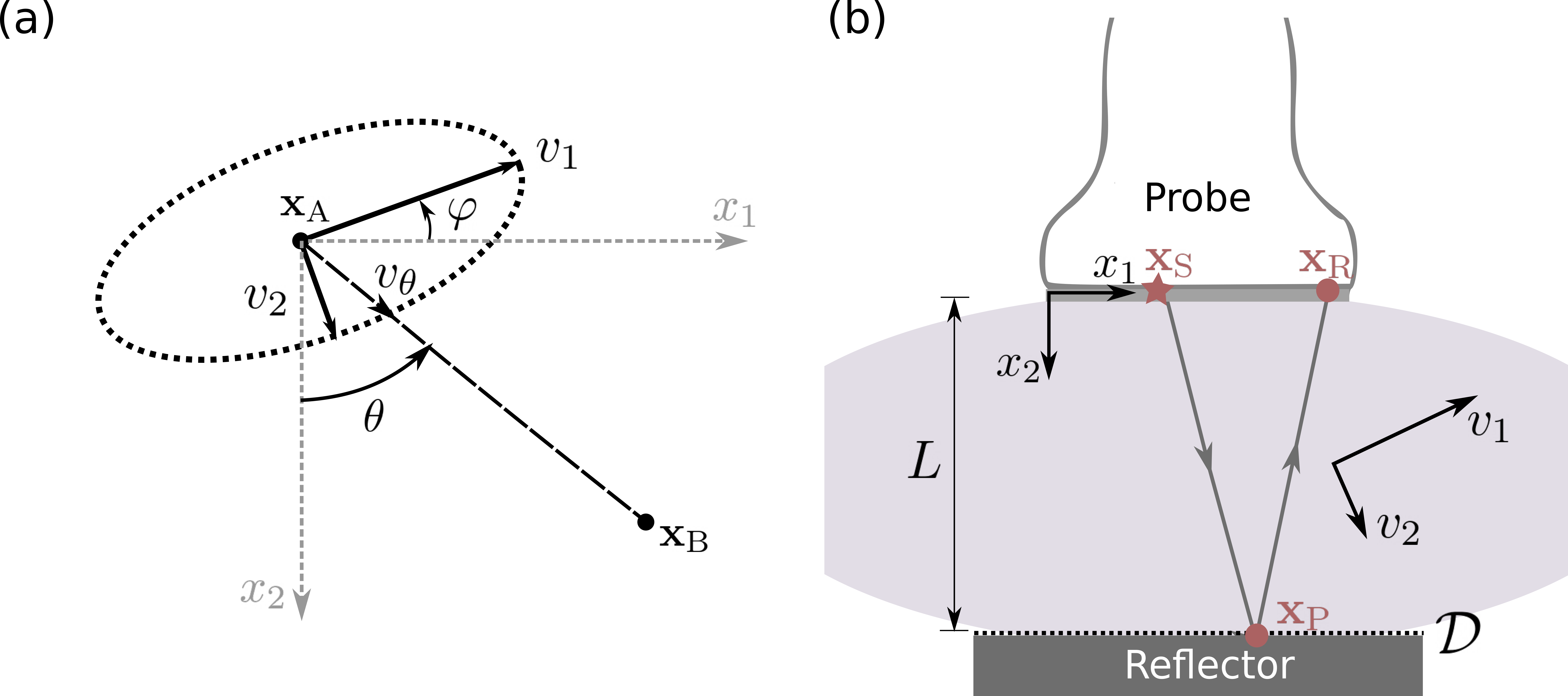
where the variables are described in the figure above. Using trigonometric identities, we find that the traveltime \(t_\text{AB}\) between positions \(\mathbf{x}_\text{A}\) and \(\mathbf{x}_\text{B}\) is given by
\begin{equation} \label{eq:traveltime} t^2_\text{AB} = \frac{1}{v^2_1}\left[(x_1^B-x_1^A)\cos{\varphi} - (x_2^B-x_2^A)\sin{\varphi} \right]^2+ \frac{1}{v^2_2}\left[(x_1^B-x_1^A)\sin{\varphi} + (x_2^B-x_2^A)\cos{\varphi}\right]^2. \end{equation}
For an experimental setup that includes a reflector located at distance \(L\) from the probe, we can measure the first-arrival reflection traveltimes and use them to retrieve muscle anisotropy. Using Fermat’s principle, we can find that, in this anisotropic medium, the reflection point will be shifted from the mid-point between the source \(\mathbf{x}_\text{S}\) and receiver \(\mathbf{x}_\text{R}\). This shift is a constant value, independent of the source and receiver location. The reflection point \(\mathbf{x}_\text{P}\) is
\begin{equation} \label{eq:reflect_point} \mathbf{x}_\text{P} = \left(\frac{x_1^S + x_1^R}{2} + \frac{L\sin2\varphi(v_2^2 - v_1^2)}{2(v_1^2 \sin^2\varphi + v_2^2 \cos^2\varphi)}, L \right), \end{equation}
where \(x_1\) indicates the first component of \(\mathbf{x}\). We can make interesting observations from this equation:
(1) The reflection point is located at the source-receiver midpoint only when the medium is isotropic (\(v_1=v_2\)) or the anisotropy symmetry axis is aligned with our coordinate system (\(\varphi = 0\)).
(2) The path with the minimum traveltime satisfies \(t_\text{SP} \left(\mathbf{x}_\text{P}\right)= t_\text{RP}\left(\mathbf{x}_\text{P}\right)\). Therefore, the fastest ray path is the path with equal traveltime along each segment.
(3) The mirror image of the receiver, namely a virtual equivalent receiver \(\tilde{R}\) below the reflector, is located at \(\mathbf{x}_{\tilde{\text{R}}} = 2\mathbf{x}_\text{P}\).
Upon combining \eqref{eq:reflect_point} and \eqref{eq:traveltime}, the first-arrival reflection traveltime between \(\mathbf{x}_\text{S}\) and \(\mathbf{x}_\text{R}\), we obtain
\begin{equation} \label{eq:ttt_total} t_\text{SR}^2 = \frac{d^2}{v^2(\theta = \pi/2)} + \frac{4L^2 v^2(\theta = \pi/2)}{v_1^2 v_2^2}, \end{equation} with \(v^2(\theta = \pi/2)\) given by \eqref{eq:Ellipse} and \(d = x_{1,\text{R}} - x_{1,\text{S}}\) being the source-receiver offset. This equation is our forward problem relating the observations \(t_\text{SR}\) and unknown muscle properties \(\mathbf{m} = (v_1,v_2,\varphi)\). Thus, the forward problem considered in this study is nonlinear unless the anisotropy symmetry axis is aligned with the coordinate system (\(\varphi = 0\)). In this case, \(t_\text{SR}^2\) becomes linearly related to squared slownesses \(1/v_1^2\) and \(1/v_2^2\).
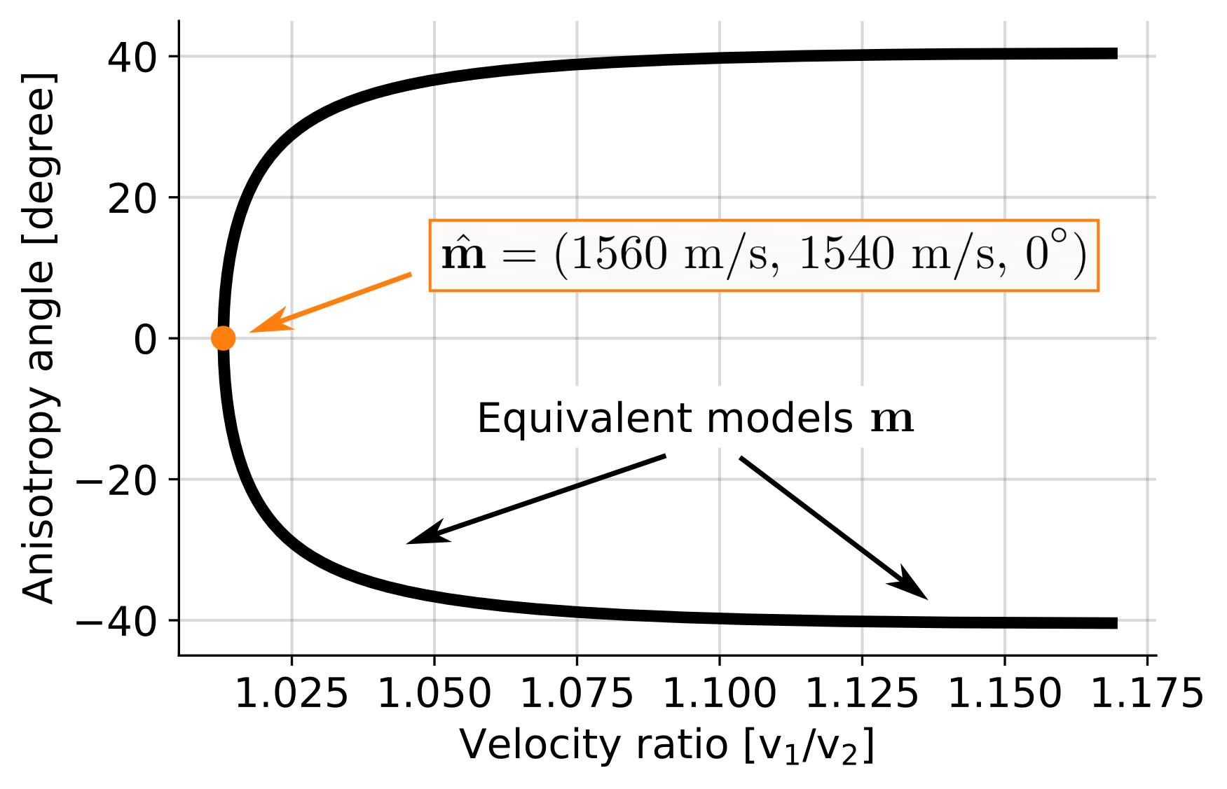
Unfortunately, this forward problem does not relate traveltimes and muscle properties uniquely. It means that different muscle properties can predict same traveltime observations:

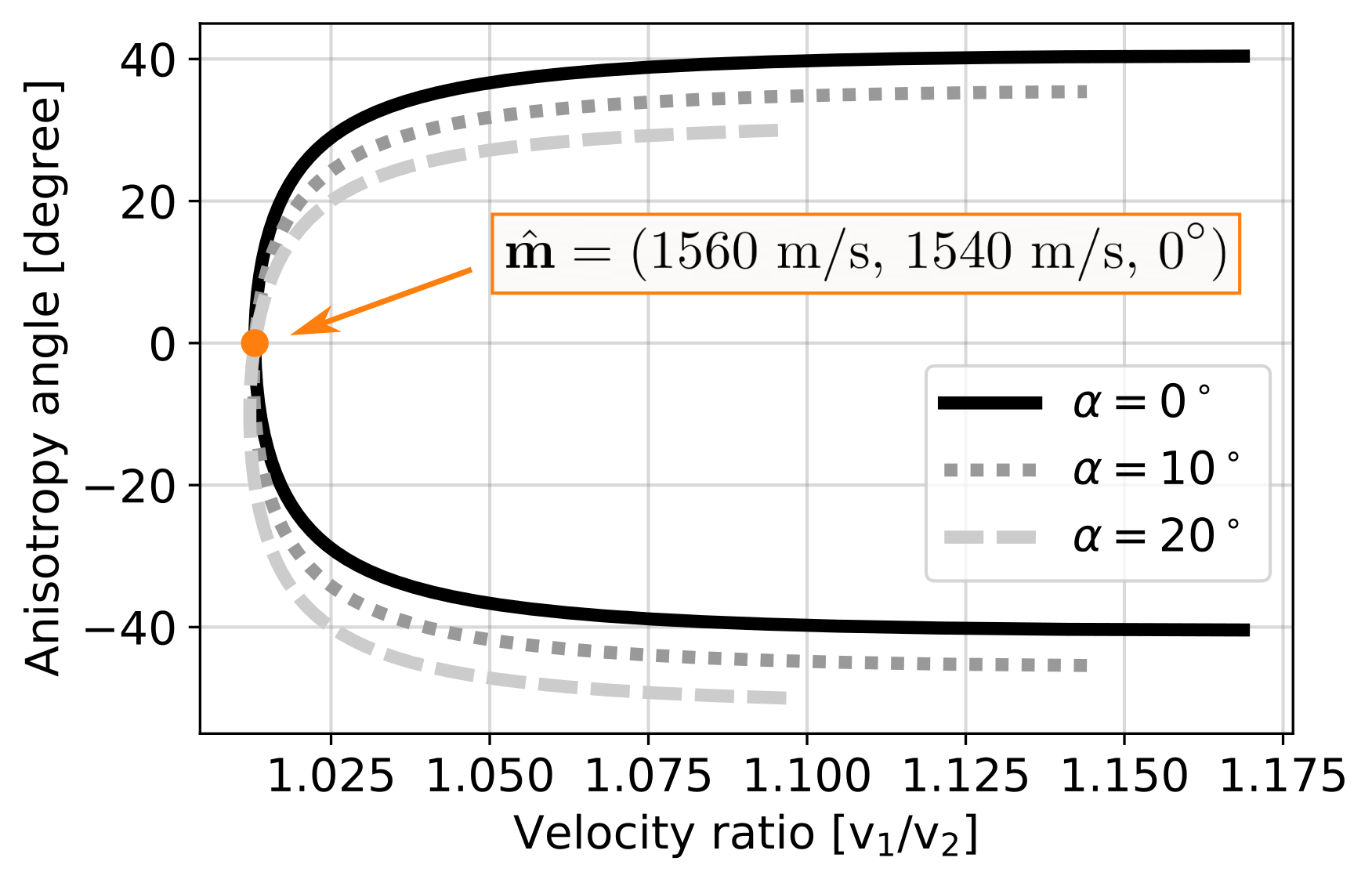
To constrain the anisotropy, we suggest taking advantage of the reflector inclination, which will generate ray paths with orientations that are different from our previous setup. We show that by combining data from multiple inclination angles we can constrain muscle anisotropy.
Following a similar approach as before, we find the following expression for first-arrival traveltimes when the reflector is inclined by \(\alpha\) with respect to \(x_1\)-axis:
\begin{equation} \label{eq:ttt_total_inclination} t_\text{SR}^2 = \frac{d^2}{v^2(\pi/2)} + \frac{4L’(L’ + d\sin\alpha)}{v_1^2 \sin^2(\varphi + \alpha) + v_2^2 \cos^2(\varphi+\alpha)}, \end{equation}
with
\begin{equation} \label{eq:Ldistance} L’ = L\cos\alpha + d_\text{S}\sin\alpha, \end{equation}
where \(d_{\text{S}}\) denotes the distance between the first element of the probe and \(\mathbf{x}_\text{S}\), and \(d\) is the distance between \(\mathbf{x}_\text{S}\) and \(\mathbf{x}_\text{R}\). This equation is the generalization of \eqref{eq:ttt_total}, which we obtain when \(\alpha = 0\).
